5.2 SubG-FSK Connection
Endpoints working in SubG-FSK mode shall be synchronized with a Gateway before an uplink or downlink transmission is performed. The synchronization mechanism works by searching for a periodic frame sent by Gateways, namely Beacon frames. Endpoints shall detect eligible Gateways by searching and receiving Beacons. In addition to its role in synchronization, Beacon payload carries basic information about the state of the Gateway, such as the Gateway’s cloud connection status, hopping seed or sequence number. The Beacon payload is not encrypted, allowing discovery and connection initiation by all Amazon Sidewalk devices. For a detailed description of the Beacon frame format and information carried by the Beacon, see section 5.1.3.1.section 5.2.1 describes the Beacon discovery mechanism that Endpoints use in initial synchronization with a Gateway.
section 5.2.2 describes how Endpoints maintain synchronization with a Gateway.
section 5.2.3 describes Endpoints’ data packet transmission scheduling in both directions.
section 5.2.4 describes the mechanism of the channel number calculation.
section 5.2.5 describes the mechanism that reduces/eliminates over the air collision.
5.2.1 Beacon discovery
The procedure of discovering nearby Gateways through their periodic Beacon transmissions is called the Beacon discovery procedure. The Beacon discovery procedure is based on traversing the channel list and performing a preamble detection on each channel. The Beacon discovery procedure is divided into two phases: preamble detection in the currently selected channel and channel change operation. If a preamble is not detected on a channel, then the Endpoint shall switch to the next channel from the list and repeat the operation. If a preamble is detected, then the Endpoint shall receive the PHY frame and check if the received frame is a Beacon frame from a Gateway eligible for connections. The duration of each phase is defined by the following:
tr_det_listening- time period used for preamble detectionch_change- time period used for switching to the next channel from the list
Note that the Beacon preamble is long enough to ensure detection regardless of the channel on which the Beacon packet is transmitted. The preamble duration is calculated by (nb_channels + 1)*(tr_det_listening + ch_change) and is greater than or equal to prm_dur. The whole PHY frame duration of the Beacon is equal to bcn_dur.
The Beacon discovery algorithm schedule is as follows:
- Select channel 0.
-
Listen to the medium on selected channel for
tr_det_listening-
if the preamble is detected, start receiving the PHY frame for a maximum duration of
bcn_durtime- if the whole PHY frame is not received within
bcn_durtime, stop receiving and go to bullet 3 - if the whole PHY frame is received within
bcn_durtime, then go to (b)
- if the whole PHY frame is not received within
-
frame is checked against being a Beacon and fitting the Beacon criteria
- if the frame is accepted and the Beacon is received, then stop the algorithm
- if the frame is not accepted, then go to bullet 3
-
if traffic is not detected, then go to bullet 3
-
-
Switch to the next channel within the
ch_changetime- if all supported channels are used, then go to bullet 1
- if not all supported channels are used, then increment the current channel by 1 and continue from bullet 2
figure 5.45 shows how the algorithm works.
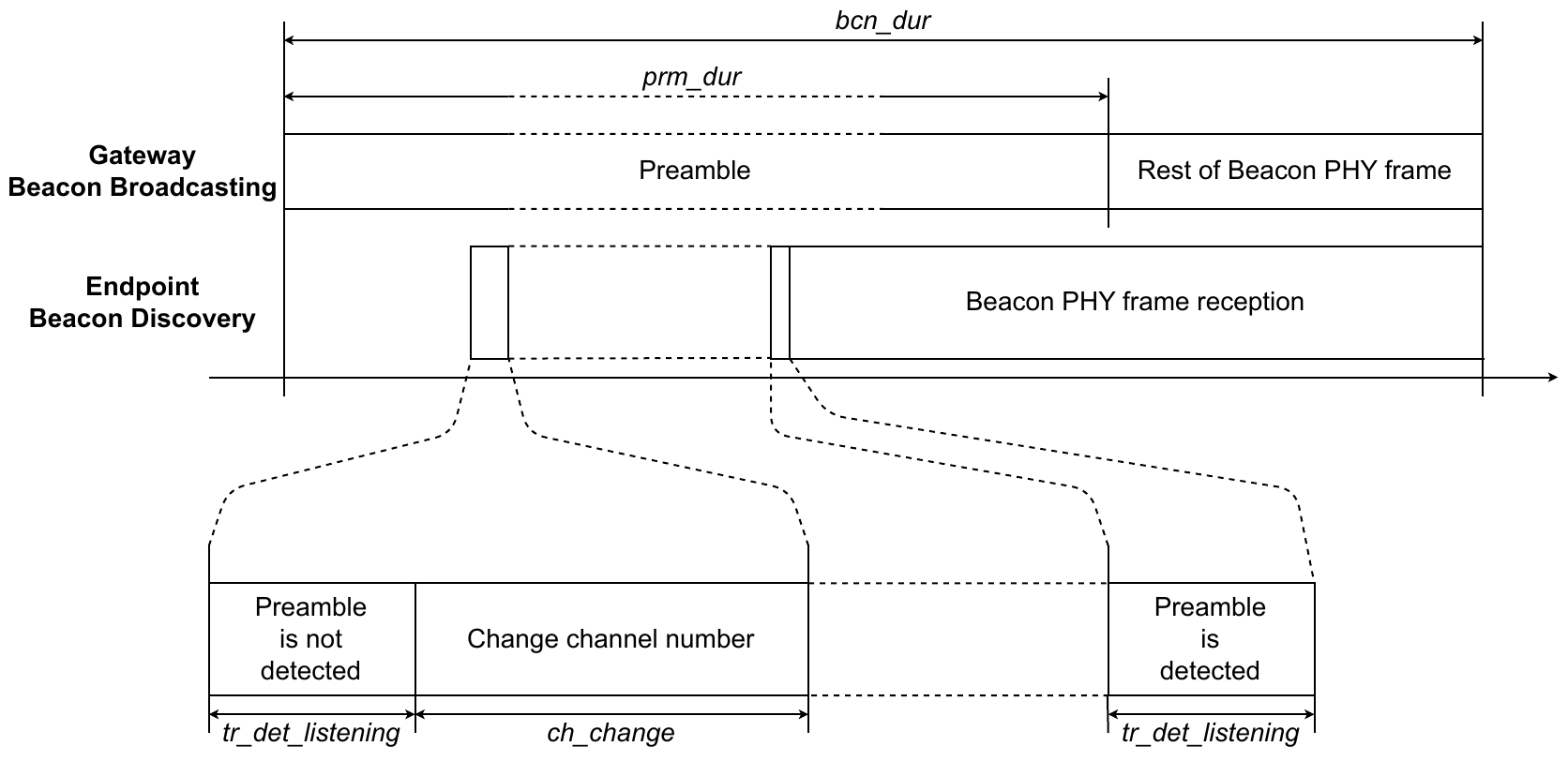
fig 5.45 SubG-FSK connection - Beacon Discovery
5.2.2 Synchronization maintenance
Based on the channel hopping algorithm, synchronized devices are capable of calculating the channel on which the next Beacon should be transmitted. Additionally, Beacons are broadcast every bcn_interval time interval so a synchronized Endpoint knows the channel and the approximate timing of the next Beacon packet. This leads to less time consumed receiving the Beacon as the synchronized device receives just the tail of the Beacon preamble transmitted by the Gateway. The Endpoint opens a downlink detection slot for each bcn_interval and listens for ongoing transmission for tr_det_listening time. When the transmission is detected, the device starts to receive the whole PHY frame and validate whether the received data is the Beacon.figure 5.46 shows the Beacon reception process on the synchronized Endpoint.
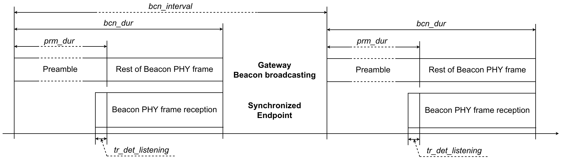
fig 5.46 SubG-FSK connection - Beacon reception
If a synchronized Endpoint fails to receive a Beacon, the Endpoint continues Link Layer operations and attempts to receive the next Beacon while the number of consecutive failures is less than 4. The third consecutive failure triggers the Beacon discovery procedure.
figure 5.47 shows the Beacon timing from the Gateway, synchronized Endpoint and the device detecting the Beacon.
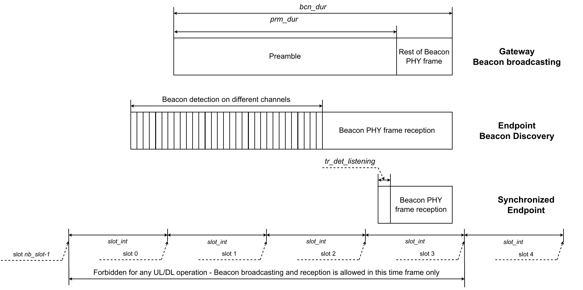
fig 5.47 SubG-FSK connection - Beacon operations
5.2.3 Uplink and downlink
An Endpoint in SubG-FSK mode shall send and receive data using Target Transmission Times. Target Transmission Times are separated by the time interval slot_int.

fig 5.48 SubG-FSK connection - Opportunities
Gateways broadcast Beacons frequently, every bcn_interval. The number of slots can be calculated based on the following equation:
nb_slot = bcn_interval / slot_int

fig 5.49 SubG-FSK connection - Opportunities and Beacon
There is one Target Transmission Time in each slot. Target transmission times can be used for both uplink and downlink. The Gateway further specifies a subset for an uplink, i.e. from an Endpoint to a Gateways, for one or a set of nodes and similarly another subset of slots for downlink transmissions from a Gateway to an Endpoint. The following slots are not used for uplink and downlink slots: 0, 1, 2 and nb_slot - 1. These are reserved for the Beacon broadcasting. Hence, the index of the first and last uplink and downlink opportunities are is 3 and is nb_slot - 2.
The subset of slots assigned for each Endpoint’s uplink and downlink transmissions are characterized by two parameters: offset and periodicity. The offset is the number of slots between slot 0 and the first slot that is scheduled for uplink or downlink. The periodicity is the time interval between subsequent slots that are scheduled for uplink or downlink. The maximum number of slots that may be used for uplink or downlink activity has the value ul_dl_nb_slot. This value can be calculated by the following equation:
ul_dl_nb_slot = nb_slot - 4 (number of slots that shall not be used for uplink and downlink slots)
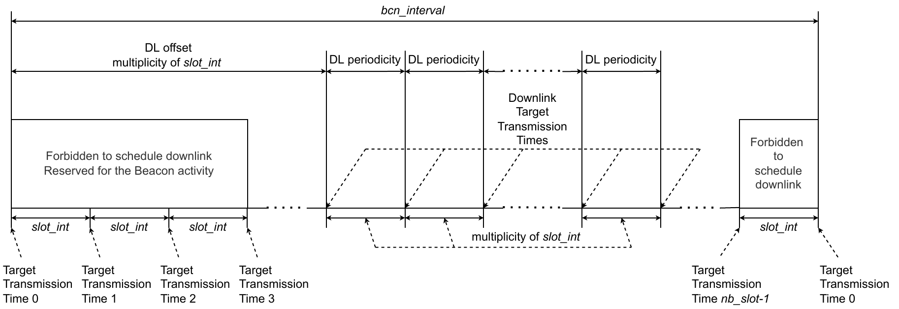
fig 5.50 SubG-FSK connection - DL scheduling
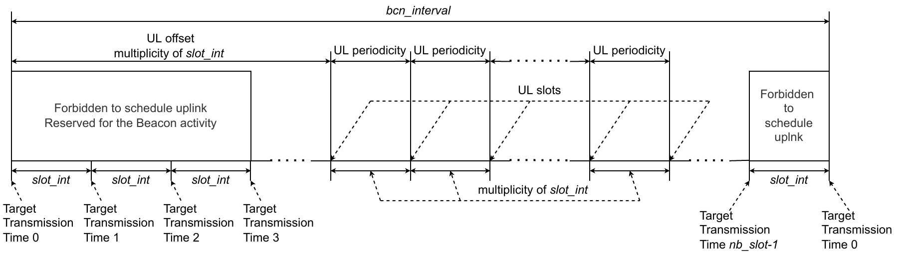
fig 5.51 SubG-FSK connection - UL scheduling
The device starting its transmission shall use a contention mechanism to sense whether the medium is free and uplink transmission may be performed.
The Endpoint shall sense the medium for the tr_det_listening duration for each Target Transmission Time and start receiving data if traffic is detected. If traffic is not detected, then the Endpoint may switch off the radio until the next scheduled uplink or downlink Target Transmission Time.
Devices working in SubG-FSK mode shall use a channel hopping mechanism for all network activities.
5.2.4 Channel hopping
The channel hopping mechanism calculates a channel number for each transmit and receive activity. The number of supported channels may differ for different regions and the number of supported channels is nb_channels. Transmission that starts in a selected slot on a channel shall finish on the same channel, even if the transmission spans following slots. The channel calculations for the Beacon broadcasting and Endpoint uplink or downlink transmissions are calculated separately. The result of the calculations is a hopping sequence that contains channel numbers for upcoming transmissions. The Beacon hopping sequence contains nb_bcn_channels elements. The uplink or downlink hopping sequence contains nb_ul_dl_channels. The hopping sequence calculations are described in section 5.2.4.3 and section 5.2.4.4. Both sequences are derived from the channel shuffler. The channel shuffler uses a pseudo random number generator. For further details, see section 5.2.4.1.
5.2.4.1 Pseudorandom number generator
The pseudorandom number generator (PRNG) produces pseudorandom values that are used in an iterative process by the channel shuffler and linear feedback shift register (LFSR) is used for that purpose. The lfsr_value[ n ] is produced by the linear-feedback shift register where n = 0, 1, 2, 3, … , nb_channels-1. LFSR is implemented as a feedback polynomial in the following shape:
x16 + x14 + x13 + x11 + 1
The feedback polynomial is used in an iterative process where output of n-1 step is the base for calculations in step n. The output value of the feedback polynomial can be calculated as follows:
msb = lfsr_value [n-1] XOR
( lfsr_value [ n - 1 ] >> 2) XOR
( lfsr_value [ n - 1 ] >> 3 ) XOR
( lfsr_value [ n - 1 ] >> 5 )
lfsr_value [ n ] = ( lfsr_value [ n - 1 ] >> 1 ) OR ( msb << 15)
The LFSR is initialized with seed and seq_id:
- 16 most significant bits of the
seedare taken:msb_seed - 16 least significant bits of the
seedare taken:lsb_seed -
the pseudo-random number generator is initialized as:
lfsr_init = msb_seedXORlsb_seedXORseq_id
The first feedback polynomial value for n = 0 is calculated based on the following:
msb = lfsr_init XOR
( lfsr_init >> 2 ) XOR
( lfsr_init >> 3 ) XOR
( lfsr_init >> 5 )
lfsr_value [ 0 ] = ( lfsr_init >> 1) OR ( msb << 15 )
The lfsr_value[ 0 ] shall be a non-zero value. In case the lfsr_value[0] value is zero, then 0xACE1 shall be used instead.
5.2.4.2 Channel shuffler
The channel shuffler produces a randomized sequence of nb_channels numbers. The channel shuffler involves a random number generator to randomize the sequence and the randomization algorithm is as follows:
- Initialize RNG with
seed,seq_id - Initialize the sequence of numbers with values: 0, 1, 2, 3, …,
nb_channels-1 - Initialize the iteration number
nwith value 0. - Calculate random value:
rng_out_value[ n ] = lfsr_value[ n ]MODnb_channels - Swap numbers from the sequence pointed out by
rng_out_value[n]andnindexes -
Increase the iteration number
n = n + 1- if
n <= nb_channels-1continue from bullet 4 - if
n > nb_channels-1stop the algorithm
- if
The schematic process of the sequence randomization is shown in 5.52.
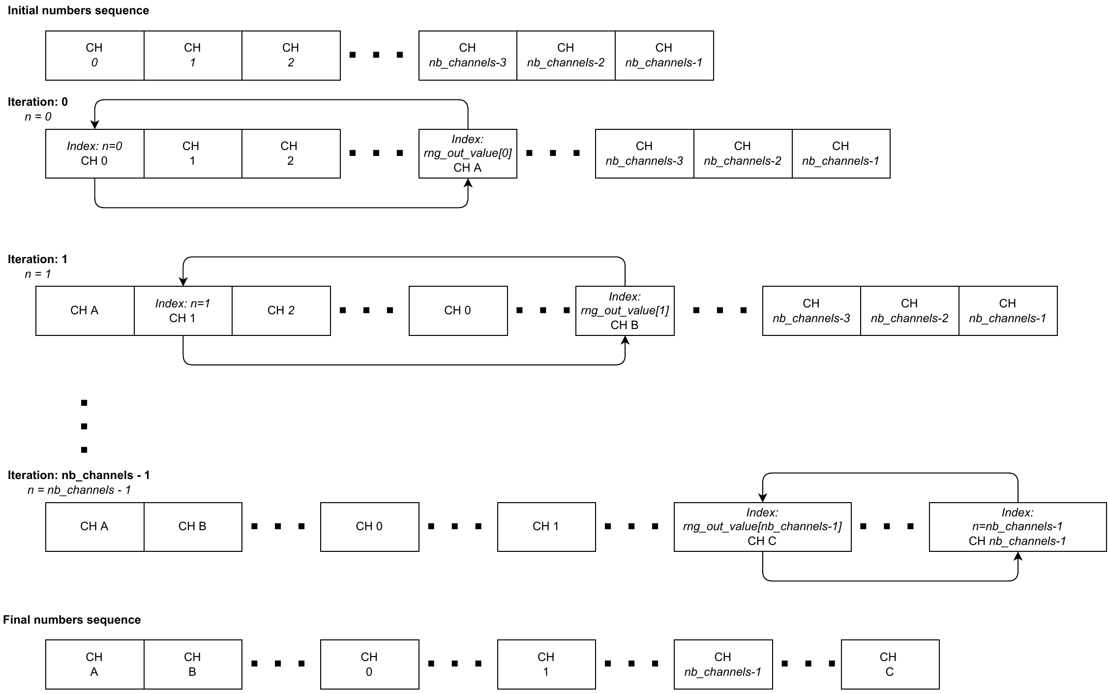
fig 5.52 SubG-FSK connection - Channels randomization process
5.2.4.3 Beacon hopping sequence calculation
Each subsequent Beacon is transmitted on a different channel. The channel number is taken from the channel hopping sequence that contains nb_channels elements. Values in the channel hopping sequence are calculated by the channel shuffler. The channel shuffler input seed is broadcast by the Beacon and can be found in the field hdr_hop_seed (see section 5.1.3.1). The channel shuffler input seq_id indicates the number of channels sequence and is calculated based on two parameters:
bcn_hop_sequence_num- the value is broadcast in the Beacon section (see 5.1.3.1)nb_channels- number of supported channels
The equation for the seq_id is as follows:
seq_id = bcn_hop_sequence_num / nb_channels
The index in the numbers sequence that points out the value indicating the channel of the received Beacon is bcn_hop_sequence_num MOD nb_channels while the upcoming Beacon channel value is pointed out by index (bcn_hop_sequence_num +1) MOD nb_channels.
The Beacon channel usage example is shown in figure 5.53. The assumptions for the figure are nb_channels = 69, bcn_hop_sequence_num starts from 0.
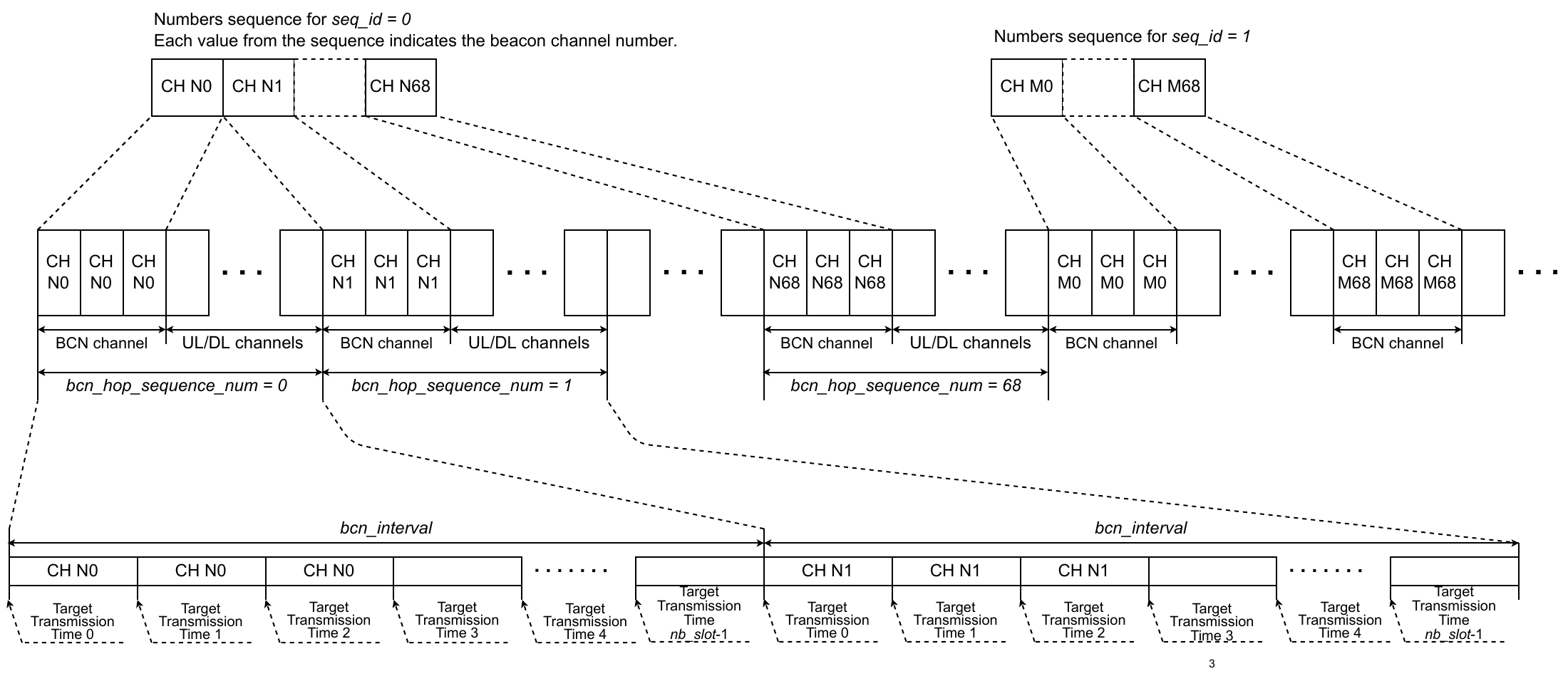
fig 5.53 SubG-FSK connection - Beacon channels
5.2.4.4 Uplink or downlink hopping sequence calculation
Subsequent slots that may be used for Endpoint uplink or downlink activity shall have different channels assigned (see section 5.2.3). The channel assignment is defined by the channel hopping sequence list that contains nb_ul_dl_channels elements. Each element indicates the channel number is seen once in the values sequence. Additionally, the channel used by Beacon broadcasting for the current bcn_interval period, channels used for nb_neighb_bcn past and future Beacons shall not be present in the uplink or downlink hopping sequence. The value of nb_ul_dl_channels can be calculated using the following equation:
nb_ul_dl_channels = nb_channels - 2*nb_neighb_bcn - 1
The base for the uplink or downlink channels sequence calculation is the channel shuffler and the Beacon hopping sequence. The channels sequence calculation starts with the channel shuffler that has two parameters: seed and seq_id. The seed value is broadcast by the Beacon and can be found in the field hdr_hop_seed (see section 5.1.3.1). The seq_id shall be calculated based on four parameters:
bcn_hop_sequence_num- the value is broadcasted in the Beaconnb_ul_dl_channels- number of channels used for uplink or downlink activitynb_slot- number of slots inbcn_intervalslot_nb- slot number (range is from 0 tonb_slot-1)
The equation for the seq_id is as follows:
seq_id = ((bcn_hop_sequence_num * nb_slot) + slot_nb) / nb_ul_dl_channels
The output of the channel shuffler is the sequence of nb_channels values. The next step is to remove the last three channels used for broadcasting Beacons, nb_neighb_bcn and the next two channels that will be used for broadcasting Beacons, nb_neighb_bcn based on the calculated Beacon hopping sequence returned by the channel shuffler. If the calculation happens during a Beacon slot, that Beacon slot is counted with the last three channels used for broadcasting Beacons. After removing Beacon channels, the final sequence of nb_ul_dl_channels values is the uplink or downlink hopping sequence.
The channel value that shall be used for the uplink or downlink slot is given by hop_seq_index value. The channel value indicates the index in the hopping sequence that corresponds to the channel number. The index value can be calculated based on the following equation:
hop_seq_index = ((bcn_hop_sequence_num * nb_slot) + slot_nb) MOD nb_ul_dl_channels
An example of uplink, downlink and the Beacon channel hopping sequence usage is shown in figure 5.54. The example has the following parameters nb_channels = 69, nb_ul_dl_channels = 64, bcn_interval = 10080 ms, slot_int = 63 ms, nb_slot = 160.
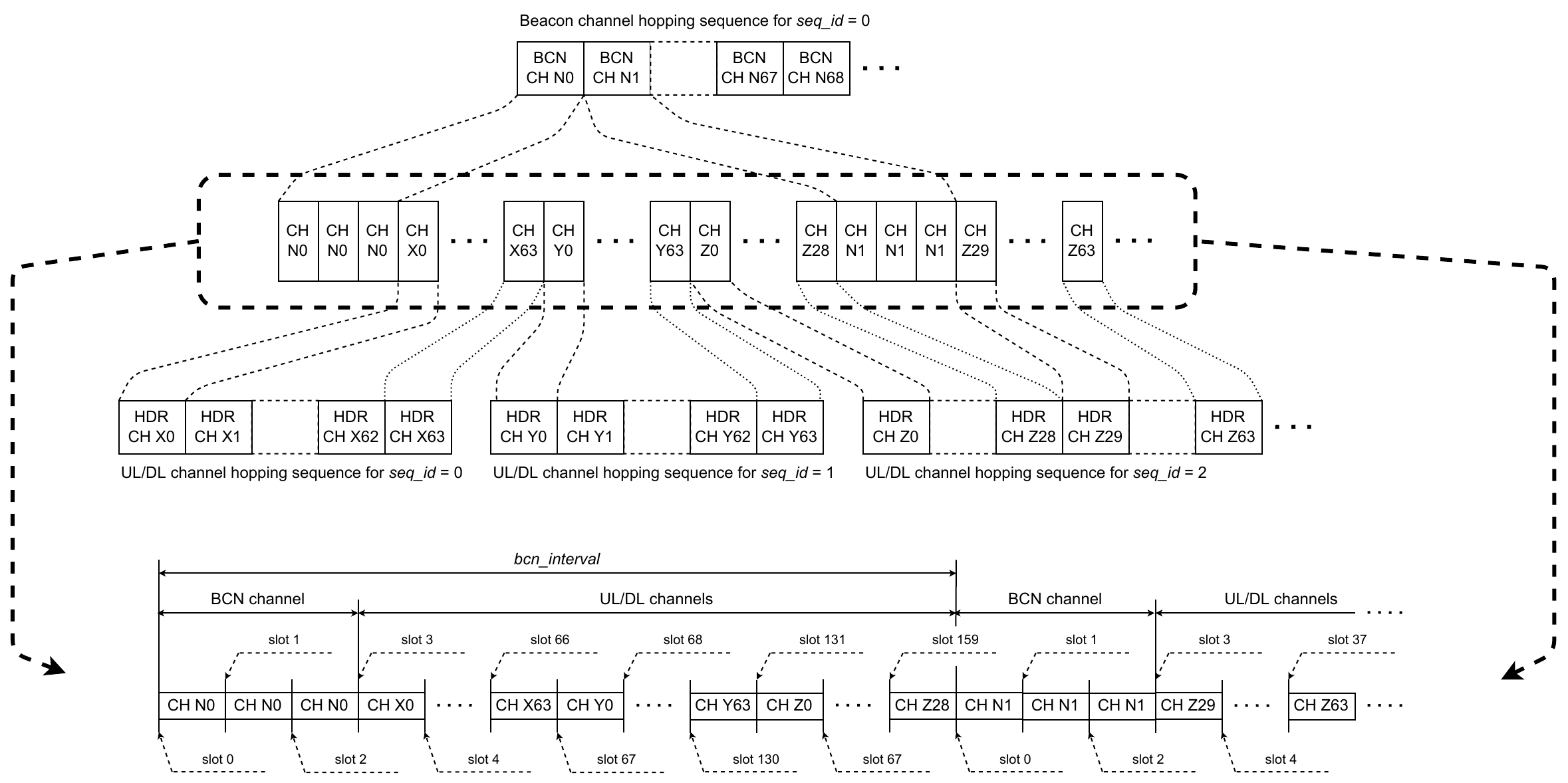
fig 5.54 SubG-FSK connection - Channel hopping usage
5.2.5 Contention mechanism
The role of the contention mechanism is to prevent a collision when two or more Endpoints start sending data in the same transmission slot. At a random time slightly before the Target Transmission Time, the device shall check whether the medium is free before transmission is started, and for that purpose a listen-before-transmit solution is used. The transmission activity is forbidden if the channel is busy and the device shall defer the transmission to a later Target Transmission Time. The transmission activity is allowed if the channel is free.
The check of medium availability is done in a contention window which precedes the target transmission time. The contention window duration has a value contend_time. The contention window is divided into 6 sub-slots. Each sub-slot has duration sub_slot_time. The number of sub-slots is defined by sub_slot_nb and the duration of each sub-slot is defined by sub_slot_time. The Endpoint has to select one sub-slot randomly. Gateways select deterministically, and always select sub_slot_nb-1. The selected slot is used for the detection of activity from other devices in the network.figure 5.55 shows the timing of contention sub-slots and uplink slots.
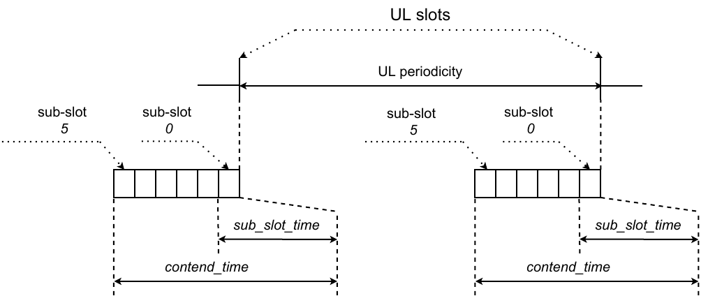
fig 5.55 SubG-FSK connection - Contention window
If the device does not detect any activity on the selected sub-slot, the device starts transmission. The transmission shall start in a subsequent sub-slot. All the remaining subsequent sub-slots shall be used for transmission of additional preamble symbols prepended to the Physical Layer frame (see section 5.1.4). If sub-slot 0 is used to detect activity, additional preamble symbols shall not be added. The actual Physical Layer frame can be started at the Target Transmission time. figure 5.56 shows when the device can start sending the data.
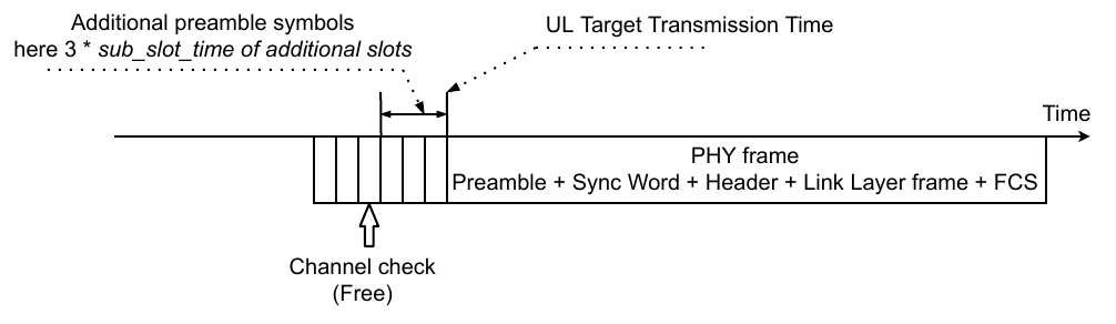
fig 5.56 SubG-FSK connection - Data transmission - Allowed
If the device detects activity on the selected sub-slot, then the device shall not start its transmission. The device shall select the next transmission slot randomly from the set of the next 4 subsequent uplink slots. At the next scheduled transmission slot, the channel availability check process needs to be performed again with a new random sub-slot selection. This process can be repeated up to tr_ret_nb times before transmission failure is concluded.figure 5.57 shows the situation when transmission needs to be deferred to a later time.
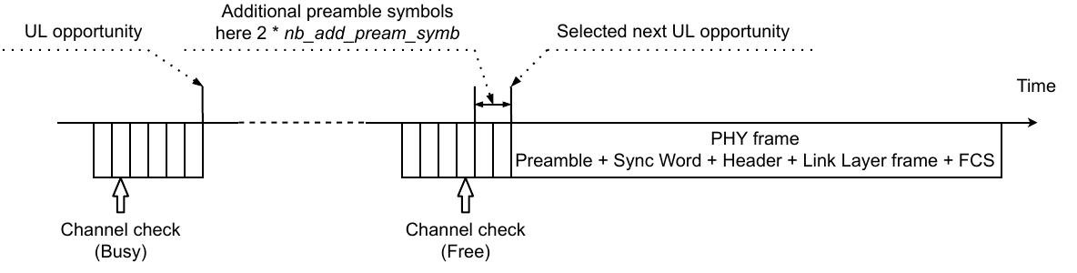
fig 5.57 SubG-FSK connection - Data transmission - Forbidden